 1. Simple Motion
 2. Accelerated Motion
 3. Projectile Motion
 4. Newton's Laws
 5. Momentum
 6. Energy
 7. Heat
 8. Electrostatics
 9. Circuits
 10. Magnetism
 11. Waves
9. Circuits
Overview
Slides
- 9.1 Intro to Electric Circuits
- 9.2 Series Circuits
- 9.3 Parallel Circuits
- 9.4 Power Concepts
- 9.5 Power Calculations
- 9.6 Complex Circuits
Skills and Understanding
- Apply Ohm's Law to calculate voltage, current, and resistance.
- Analyze series and parallel circuits, including calculating resistance of complex arrangements of resistors.
- Determine the power used in a circuit or in components of a circuit.
Equations
\[ \begin{array}{cc} V = IR \quad \quad \quad \quad P = IV \\ R = R_{1} + \dots + R_{n} \quad \quad \quad \quad \frac{1}{R} = \frac{1}{R_{1}} + \dots + \frac{1}{R_{n}} \\ \end{array} \]Vocabulary
- Voltage \(V\) is an electric potential, measured in volts (V).
- Current \(I\) is the flow of electric charge, measured in amperes (A) or "amps".
- Resistance \(R\) is an opposition to the flow of current, measured in ohms (\(\Omega\)).
- Power \(P\) is the rate at which electrical energy is transferred within a circuit, measured in watts (W).
- A Series circuit is one in which the components are arranged one after another, where the output of one component leads to the input of the next.
- A Parallel circuit is one in which the components are arranged so that their inputs are connected and their outputs are connected. The diagram of such an arrangement shows the components to be parallel to one another.
9.1 Intro to Circuits
An electric circuit is a closed loop through which electric current can flow. It consists of electrical components including resistors, capacitors, switches, and power sources like batteries. Three fundamental properties of circuits are current, voltage, and resistance.
- Current (I) refers to the flow of electric charge, and is measured in amperes (A). It is the rate of change of charge per time, \(I = \frac{\Delta q}{\Delta t}\), where \(\Delta q\) is the change in charge.
- Voltage (V) is an electric potential measured in volts (V), and can be thought of as a pressure that "pushes" on charge to create current. Increasing voltage increases current.
- Resistance (R) is an opposition to the flow of current, measured in ohms (\(\Omega\)). Increasing resistance decreases current.
Circuit Diagrams
The circuit diagram below depicts a circuit with two components: a voltage source (battery) on the left, and a resistor on the right. They are connected by wire (lines).
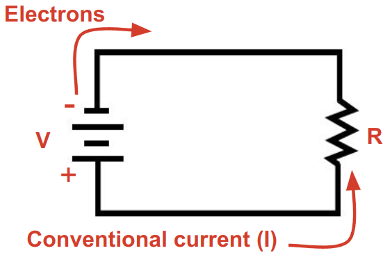
We analyze current as "moving" in the positive direction, even though physically the positive charges are stationary while electrons are flowing from the negative (-) side of the battery toward the positive (+) side.
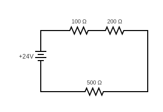
9.2 Series Circuits
A series circuit is one where the components are connected in a series. That is, one after another so that the output of one component leads to the input of the next.
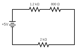
Equivalent Resistance
Imagine replacing all of the resistors in the circuit above with a single resistor with the same overall resistance. We call this equivalent resistance. For a series of resistors \(R_{1}\), \(R_{2}\), ..., \(R_{n}\), the equivalent resistance is the sum of all thre resistances: \[R = R_{1} + R_{2} + \dots + R_{n} \] For the circuit above we would get \(R = 1200 + 800 + 2000 = 4000 \Omega \)
9.3 Parallel Circuits
9.4 Power
Electric power is the rate at which energy is used by a circuit or circuit component. Power is measured in Watts \(W\), which is equivalent to Joules per second. Power is the product of current and voltage, \[ P = IV \] We can find the total power in a circuit, or the power used by individual components.
9.5 Complex Circuits